Rendering
In this chapter we will learn the processes that takes place while rendering a scene using OpenGL. If you are used to older versions of OpenGL, that is fixed-function pipeline, you may end this chapter wondering why it needs to be so complex. You may end up thinking that drawing a simple shape to the screen should not require so many concepts and lines of code. Let me give you an advice for those of you that think that way. It is actually simpler and much more flexible. You only need to give it a chance. Modern OpenGL lets you think in one problem at a time and it lets you organize your code and processes in a more logical way.
The sequence of steps that ends up drawing a 3D representation into your 2D screen is called the graphics pipeline. First versions of OpenGL employed a model which was called fixed-function pipeline. This model employed a set of steps in the rendering process which defined a fixed set of operations. The programmer was constrained to the set of functions available for each step. Thus, the effects and operations that could be applied were limited by the API itself (for instance, “set fog” or “add light”, but the implementation of those functions were fixed and could not be changed).
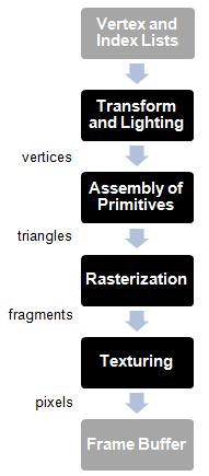
The graphics pipeline was composed of these steps:
OpenGL 2.0 introduced the concept of programmable pipeline. In this model, the different steps that compose the graphics pipeline can be controlled or programmed by using a set of specific programs called shaders. The following picture depicts a simplified version of the OpenGL programmable pipeline:
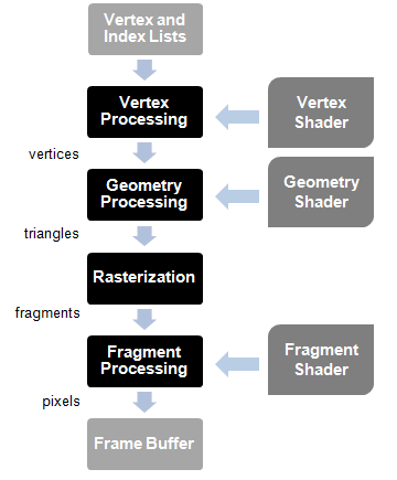
The rendering starts taking as its input a list of vertices in the form of Vertex Buffers. But, what is a vertex? A vertex is a data structure that describes a point in 2D or 3D space. And how do you describe a point in a 3D space? By specifying its x, y and z coordinates. And what is a Vertex Buffer? A Vertex Buffer is another data structure that packs all the vertices that need to be rendered, by using vertex arrays, and makes that information available to the shaders in the graphics pipeline.
Those vertices are processed by the vertex shader whose main purpose is to calculate the projected position of each vertex into the screen space. This shader can generate also other outputs related to colour or texture, but its main goal is to project the vertices into the screen space, that is, to generate dots.
The geometry processing stage connects the vertices that are transformed by the vertex shader to form triangles. It does so by taking into consideration the order in which the vertices were stored and grouping them using different models. Why triangles? A triangle is like the basic work unit for graphic cards. It’s a simple geometric shape that can be combined and transformed to construct complex 3D scenes. This stage can also use a specific shader to group the vertices.
The rasterization stage takes the triangles generated in the previous stages, clips them and transforms them into pixel-sized fragments.
Those fragments are used during the fragment processing stage by the fragment shader to generate pixels assigning them the final color that gets written into the framebuffer. The framebuffer is the final result of the graphics pipeline. It holds the value of each pixel that should be drawn to the screen.
Keep in mind that 3D cards are designed to parallelize all the operations described above. The input data can be processes in parallel in order to generate the final scene.
So let's start writing our first shader program. Shaders are written by using the GLSL language (OpenGL Shading Language) which is based on ANSI C. First we will create a file named “vertex.vs” (The extension is for Vertex Shader) under the resources directory with the following content:
#version 330

layout (location=0) in vec3 position;

void main()
{
    gl_Position = vec4(position, 1.0);
}
The first line is a directive that states the version of the GLSL language we are using. The following table relates the GLSL version, the OpenGL that matches that version and the directive to use (Wikipedia: https://en.wikipedia.org/wiki/OpenGL_Shading_Language#Versions).
| GLS Version | OpenGL Version | Shader Preprocessor |
|---|---|---|
| 1.10.59 | 2.0 | #version 110 |
| 1.20.8 | 2.1 | #version 120 |
| 1.30.10 | 3.0 | #version 130 |
| 1.40.08 | 3.1 | #version 140 |
| 1.50.11 | 3.2 | #version 150 |
| 3.30.6 | 3.3 | #version 330 |
| 4.00.9 | 4.0 | #version 400 |
| 4.10.6 | 4.1 | #version 410 |
| 4.20.11 | 4.2 | #version 420 |
| 4.30.8 | 4.3 | #version 430 |
| 4.40 | 4.4 | #version 440 |
| 4.50 | 4.5 | #version 450 |
The second line specifies the input format for this shader. Data in an OpenGL buffer can be whatever we want, that is, the language does not force you to pass a specific data structure with a predefined semantic. From the point of view of the shader it is expecting to receive a buffer with data. It can be a position, a position with some additional information or whatever we want. The vertex shader is just receiving an array of floats. When we fill the buffer, we define the buffer chunks that are going to be processed by the shader.
So, first we need to get that chunk into something that’s meaningful to us. In this case we are saying that, starting from the position 0, we are expecting to receive a vector composed of 3 attributes (x, y, z).
The shader has a main block like any other C program which in this case is very simple. It is just returning the received position in the output variable gl_Position without applying any transformation. You now may be wondering why the vector of three attributes has been converted into a vector of four attributes (vec4). This is because gl_Position is expecting the result in vec4 format since it is using homogeneous coordinates. That is, it’s expecting something in the form (x, y, z, w), where w represents an extra dimension. Why add another dimension? In later chapters you will see that most of the operations we need to do are based on vectors and matrices. Some of those operations cannot be combined if we do not have that extra dimension. For instance we could not combine rotation and translation operations. (If you want to learn more on this, this extra dimension allow us to combine affine and linear transformations. You can learn more about this by reading the excellent book “3D Math Primer for Graphics and Game development, by Fletcher Dunn and Ian Parberry).
Let us now have a look at our first fragment shader. We will create a file named “fragment.fs” (The extension is for Fragment Shader) under the resources directory with the following content:
#version 330

out vec4 fragColor;

void main()
{
    fragColor = vec4(0.0, 0.5, 0.5, 1.0);
}
The structure is quite similar to our vertex shader. In this case we will set a fixed colour for each fragment. The output variable is defined in the second line and set as a vec4 fragColor.
Now that we have our shaders created, how do we use them? This is the sequence of steps we need to follow:
- Create a OpenGL Program
- Load the vertex and fragment shader code files.
- For each shader, create a new shader program and specify its type (vertex, fragment).
- Compile the shader.
- Attach the shader to the program.
- Link the program.
At the end the shader will be loaded in the graphics card and we can use it by referencing an identifier, the program identifier.
package org.lwjglb.engine.graph;

import static org.lwjgl.opengl.GL20.*;

public class ShaderProgram {

    private final int programId;

    private int vertexShaderId;

    private int fragmentShaderId;

    public ShaderProgram() throws Exception {
        programId = glCreateProgram();
        if (programId == 0) {
            throw new Exception("Could not create Shader");
        }
    }

    public void createVertexShader(String shaderCode) throws Exception {
        vertexShaderId = createShader(shaderCode, GL_VERTEX_SHADER);
    }

    public void createFragmentShader(String shaderCode) throws Exception {
        fragmentShaderId = createShader(shaderCode, GL_FRAGMENT_SHADER);
    }

    protected int createShader(String shaderCode, int shaderType) throws Exception {
        int shaderId = glCreateShader(shaderType);
        if (shaderId == 0) {
            throw new Exception("Error creating shader. Type: " + shaderType);
        }

        glShaderSource(shaderId, shaderCode);
        glCompileShader(shaderId);

        if (glGetShaderi(shaderId, GL_COMPILE_STATUS) == 0) {
            throw new Exception("Error compiling Shader code: " + glGetShaderInfoLog(shaderId, 1024));
        }

        glAttachShader(programId, shaderId);

        return shaderId;
    }

    public void link() throws Exception {
        glLinkProgram(programId);
        if (glGetProgrami(programId, GL_LINK_STATUS) == 0) {
            throw new Exception("Error linking Shader code: " + glGetProgramInfoLog(programId, 1024));
        }

        if (vertexShaderId != 0) {
            glDetachShader(programId, vertexShaderId);
        }
        if (fragmentShaderId != 0) {
            glDetachShader(programId, fragmentShaderId);
        }

        glValidateProgram(programId);
        if (glGetProgrami(programId, GL_VALIDATE_STATUS) == 0) {
            System.err.println("Warning validating Shader code: " + glGetProgramInfoLog(programId, 1024));
        }

    }

    public void bind() {
        glUseProgram(programId);
    }

    public void unbind() {
        glUseProgram(0);
    }

    public void cleanup() {
        unbind();
        if (programId != 0) {
            glDeleteProgram(programId);
        }
    }
}
The constructor of the ShaderProgram creates a new program in OpenGL and provides methods to add vertex and fragment shaders. Those shaders are compiled and attached to the OpenGL program. When all shaders are attached the link method should be invoked which links all the code and verifies that everything has been done correctly.
Once the shader program has been linked, the compiled vertex and fragment shaders can be freed up (by calling glDetachShader)
Regarding verification, this is done through the glValidateProgram call. This method is used mainly for debugging purposes, and it should be removed when your game reaches production stage. This method tries to validate if the shader is correct given the current OpenGL state. This means, that validation may fail in some cases even if the shader is correct, due to the fact that the current state is not complete enough to run the shader (some data may have not been uploaded yet). So, instead of failing, we just print an error message to the standard error output.
ShaderProgram also provides methods to activate this program for rendering (bind) and to stop using it (unbind). Finally it provides a cleanup method to free all the resources when they are no longer needed.
Since we have a cleanup method, let us change our IGameLogic interface class to add a cleanup method:
void cleanup();
This method will be invoked when the game loop finishes, so we need to modify the run method of the GameEngine class:
@Override
public void run() {
    try {
        init();
        gameLoop();
    } catch (Exception excp) {
        excp.printStackTrace();
    } finally {
        cleanup();
    }
}
Now we can use our shaders in order to display a triangle. We will do this in the init method of our Renderer class. First of all, we create the shader program:
public void init() throws Exception {
    shaderProgram = new ShaderProgram();
    shaderProgram.createVertexShader(Utils.loadResource("/vertex.vs"));
    shaderProgram.createFragmentShader(Utils.loadResource("/fragment.fs"));
    shaderProgram.link();
}
We have created a utility class which by now provides a method to retrieve the contents of a file from the class path. This method is used to retrieve the contents of our shaders.
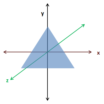
Now we can define our triangle as an array of floats. We create a single float array which will define the vertices of the triangle. As you can see there’s no structure in that array. As it is right now, OpenGL cannot know the structure of that data. It’s just a sequence of floats:
float[] vertices = new float[]{
     0.0f,  0.5f, 0.0f,
    -0.5f, -0.5f, 0.0f,
     0.5f, -0.5f, 0.0f
};
The following picture depicts the triangle in our coordinates system.
Now that we have our coordinates, we need to store them into our graphics card and tell OpenGL about the structure. We will introduce now two important concepts, Vertex Array Objects (VAOs) and Vertex Buffer Object (VBOs). If you get lost in the next code fragments remember that at the end what we are doing is sending the data that models the objects we want to draw to the graphics card memory. When we store it we get an identifier that serves us later to refer to it while drawing.
Let us first start with Vertex Buffer Object (VBOs). A VBO is just a memory buffer stored in the graphics card memory that stores vertices. This is where we will transfer our array of floats that model a triangle. As we said before, OpenGL does not know anything about our data structure. In fact it can hold not just coordinates but other information, such as textures, colour, etc.
A Vertex Array Objects (VAOs) is an object that contains one or more VBOs which are usually called attribute lists. Each attribute list can hold one type of data: position, colour, texture, etc. You are free to store whichever you want in each slot.
A VAO is like a wrapper that groups a set of definitions for the data that is going to be stored in the graphics card. When we create a VAO we get an identifier. We use that identifier to render it and the elements it contains using the definitions we specified during its creation.
So let us continue coding our example. The first thing that we must do is to store our array of floats into a FloatBuffer. This is mainly due to the fact that we must interface with the OpenGL library, which is C-based, so we must transform our array of floats into something that can be managed by the library.
FloatBuffer verticesBuffer = MemoryUtil.memAllocFloat(vertices.length);
verticesBuffer.put(vertices).flip();
We use the MemoryUtil class to create the buffer in off-heap memory so that it's accessible by the OpenGL library. After we have stored the data (with the put method) we need to reset the position of the buffer to the 0 position with the flip method (that is, we say that we’ve finishing writing to it). Remember, that Java objects, are allocated in a space called the heap. The heap is a large bunch of memory reserved in the JVM's process memory. Memory stored in the heap cannot be accessed by native code (JNI, the mechanism that allows calling native code from Java does not allow that). The only way of sharing memory data between Java and native code is by directly allocating memory in Java.
If you come from previous versions of LWJGL it's important to stress out a few topics. You may have noticed that we do not use the utility class BufferUtils to create the buffers. Instead we use the MemoryUtil class. This is due to the fact that BufferUtils was not very efficient, and has been mantained only for backwards compatibility. Instead, LWJGL 3 proposes two methods for buffer management:
- Auto-managed buffers, that is, buffers that are automatically collected by the Garbage Collector. These buffers are mainly used for short lived operations, or for data that is transferred to the GPU and does not need to be present in the process memory. This is achieved by using the
org.lwjgl.system.MemoryStackclass. - Manually managed buffers. In this case we need to carefulley free them once we are finished. These buffers are intended for long time operations or for large amounts of data. This is achieved by using the
MemoryUtilclass.
You can consult the details here: https://blog.lwjgl.org/memory-management-in-lwjgl-3/.
In this case, our data is sent to the GPU so we could use auto-managed buffers. But since, later on, we will use them to hold potentially large volumes of data we will need to manually manage them. This is the reason why we are using the MemoryUtil class and thus, why we are freeing the buffer in a finally block. In next chapters we will learn how to use auto-managed buffers.
Now we need to create the VAO and bind it.
vaoId = glGenVertexArrays();
glBindVertexArray(vaoId);
Then we need to create the VBO, bind it and put the data into it.
vboId = glGenBuffers();
glBindBuffer(GL_ARRAY_BUFFER, vboId);
glBufferData(GL_ARRAY_BUFFER, verticesBuffer, GL_STATIC_DRAW);
memFree(verticesBuffer);
Now comes the most important part. We need to define the structure of our data and store it in one of the attribute lists of the VAO. This is done with the following line.
glVertexAttribPointer(0, 3, GL_FLOAT, false, 0, 0);
The parameters are:
- index: Specifies the location where the shader expects this data.
- size: Specifies the number of components per vertex attribute (from 1 to 4). In this case, we are passing 3D coordinates, so it should be 3.
- type: Specifies the type of each component in the array, in this case a float.
- normalized: Specifies if the values should be normalized or not.
- stride: Specifies the byte offset between consecutive generic vertex attributes. (We will explain it later).
- offset: Specifies an offset to the first component in the buffer.
After we are finished with our VBO we can unbind it and the VAO (bind them to 0)
// Unbind the VBO
glBindBuffer(GL_ARRAY_BUFFER, 0);

// Unbind the VAO
glBindVertexArray(0);
Once this has been completed we must free the off-heap memory that was allocated by the FloatBuffer. This is done by manually calling memFree, as Java garbage collection will not clean up off-heap allocations.
if (verticesBuffer != null) {
    MemoryUtil.memFree(verticesBuffer);
}
That’s all the code that should be in our init method. Our data is already in the graphics card, ready to be used. We only need to modify our render method to use it each render step during our game loop.
public void render(Window window) {
    clear();

    if ( window.isResized() ) {
        glViewport(0, 0, window.getWidth(), window.getHeight());
        window.setResized(false);
    }

    shaderProgram.bind();

    // Bind to the VAO
    glBindVertexArray(vaoId);
    glEnableVertexAttribArray(0);

    // Draw the vertices
    glDrawArrays(GL_TRIANGLES, 0, 3);

    // Restore state
    glDisableVertexAttribArray(0);
    glBindVertexArray(0);

    shaderProgram.unbind();
}
As you can see we just clear the window, bind the shader program, bind the VAO, draw the vertices stored in the VBO associated to the VAO and restore the state. That’s it.
We also added a cleanup method to our Renderer class which frees acquired resources.
public void cleanup() {
    if (shaderProgram != null) {
        shaderProgram.cleanup();
    }

    glDisableVertexAttribArray(0);

    // Delete the VBO
    glBindBuffer(GL_ARRAY_BUFFER, 0);
    glDeleteBuffers(vboId);

    // Delete the VAO
    glBindVertexArray(0);
    glDeleteVertexArrays(vaoId);
}
And, that’s all! If you followed the steps carefully you will see something like this.
Our first triangle! You may think that this will not make it into the top ten game list, and you will be totally right. You may also think that this has been too much work for drawing a boring triangle. But keep in mind that we are introducing key concepts and preparing the base infrastructure to do more complex things. Please be patient and continue reading.